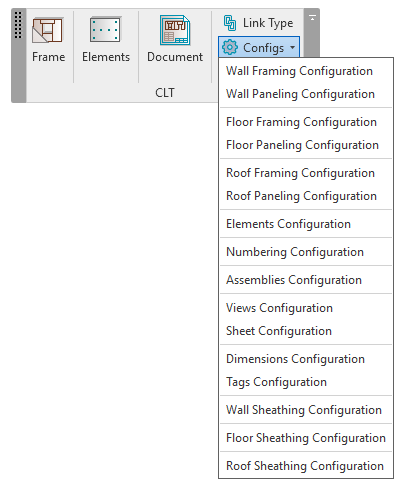
# Workflow - Step by Step

We want to make it as simple as possible for you to try out our CLT solution on your own. In this article, I’ll go through the basic steps to follow so that your use of the software is as hassle-free as possible.

{% hint style="info" %}
*Since these instructions are meant to simplify **testing** of Wood Framing CLT, I have used our sample configurations and families throughout.*

*Just keep in mind that **all these sample rules can be modified to your own needs and standards.***
{% endhint %}

I’ll be referring to these functions throughout this article:

**Tools and functions of Wood Framing CLT**

<figure><img src="https://239424168-files.gitbook.io/~/files/v0/b/gitbook-x-prod.appspot.com/o/spaces%2FqtUsszuAWXIZhQhrvjnb%2Fuploads%2FA7Tvd7MPe3na9lKfPMUF%2F1.png?alt=media&#x26;token=89bcbb68-9f2f-4cfd-9528-afe3f7cc92ba" alt="" width="563"><figcaption></figcaption></figure>

In the ribbon, there are six top-level functions:

<table><thead><tr><th width="151"></th><th></th><th data-hidden></th><th data-hidden></th></tr></thead><tbody><tr><td><strong>Frame</strong></td><td>Functionality needed for modeling frames with CLT panels</td><td></td><td></td></tr><tr><td><strong>Elements</strong></td><td>Functionality needed for creating connections common for CLT structures</td><td></td><td></td></tr><tr><td><strong>Document</strong></td><td>Functionality needed for numbering elements and creating shop drawings
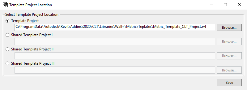
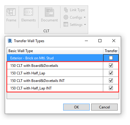
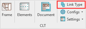
</td><td></td><td></td></tr><tr><td><strong>Link Type</strong></td><td>Use this to create links for walls, floors, and roofs.</td><td></td><td></td></tr><tr><td><strong>Configs</strong></td><td>Enter, create and modify all needed rules for modeling, numbering, dimensioning, etc.
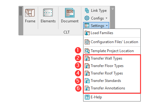
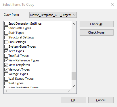
</td><td></td><td></td></tr><tr><td><strong>Settings</strong></td><td>Load all needed families for CLT Structures automatically, browse configuration files’ locations, and transfer element types and standards.</td><td></td><td></td></tr></tbody></table>

## Example workflow for CLT project creation in Revit

After starting a new Revit project, make sure you save it.   ![icon](https://agacad.com/wp-content/uploads/2022/05/Save-icon.png)

{% hint style="info" %}
By the way, the 9 STEPS outlined below can be seen in this tutorial video:
{% endhint %}

{% embed url="<https://youtu.be/-Wg_hLrz-cU>" %}

### **STEP 1: Load families**

Choose the sample families to be loaded into the current project. **Wood Framing CLT** provides sample **Metric** and **Imperial** families for creating frames with connections common for CLT structures, tag families, and sample schedules.

<figure><img src="https://239424168-files.gitbook.io/~/files/v0/b/gitbook-x-prod.appspot.com/o/spaces%2FqtUsszuAWXIZhQhrvjnb%2Fuploads%2FwHZkVlRtBQqSkyccn4ln%2FSelect-family-catalogs-for-loading.png?alt=media&#x26;token=177ea719-4887-460b-a99f-04994ce62d5c" alt=""><figcaption></figcaption></figure>

<table><thead><tr><th>If you’ll be designing only the CLT structure, loading families from CLT Catalogs is sufficient:</th><th>Optional sample family catalogs:</th><th data-hidden></th></tr></thead><tbody><tr><td><mark style="color:purple;"><strong>CLT Catalogs</strong></mark></td><td><mark style="color:purple;"><strong>Floor, Roof &#x26; Wall Catalogs</strong></mark></td><td></td></tr><tr><td><strong>CLT Families</strong> – sample families for creating frames with connections common for CLT structures</td><td><strong>Additional Families</strong> – sample families for creating additional floor/roof/wall layers, like timber secondary frames, horizontal or vertical nailers, battens, etc. or main timber frames with studs/joists</td><td></td></tr><tr><td><strong>CLT Schedules</strong> – sample schedules for CLT panels</td><td><strong>Additional Schedules</strong> – sample schedules for floor/roof/wall additional layers</td><td></td></tr><tr><td><strong>Tag Families</strong> – sample tag families</td><td><strong>Finish Families</strong> – sample families for creating floor/roof/wall finish layers, like flooring, roofing, siding</td><td></td></tr></tbody></table>

### **STEP 2: Transfer standards**

‘Template Project’ is a Revit file with sample Wall, Floor and Roof types, standards, and annotations. The ‘Template Project’ feature allows users to transfer all needed information from a template project, eliminating the need to create Wall/Floor/Roof types and other needed elements or standards from scratch for every new project.

<figure><img src="https://agacad.com/wp-content/uploads/2022/05/Transfer-project-standards.png" alt="software UI"><figcaption></figcaption></figure>

So, before working with the software, we recommend using these features (numbers 2-6 in the image above).

1. **Template Project Location** – the path to your template project. Wood Framing CLT comes with a sample Template Project, which is mapped here automatically.

{% hint style="info" %}
*When starting out, we recommend using the sample template project that comes with the software and is automatically mapped already. Later on, of course, you can create and use your own.*
{% endhint %}

<figure><img src="https://agacad.com/wp-content/uploads/2022/05/Template-project-location.png" alt="software UI"><figcaption></figcaption></figure>

2\. **Transfer Wall Types** – transfer wall types from the projects which is defined in ‘Template Project Location’ to the current project.

3\. **Transfer Floor Types** – transfer floor types from the projects which is defined in ‘Template Project Location’ to the current project.

4\. **Transfer Roof Types** – transfer roof types from the projects which is defined in ‘Template Project Location’ to the current project.

{% hint style="info" %}
For steps 2-4 (above), you can transfer only the types containing ‘CLT’ in their name.
{% endhint %}

*An example using the metric sample template project and ‘Transfer Wall Types’:*

<figure><img src="https://agacad.com/wp-content/uploads/2022/05/Transfer-Wall-types.png" alt="software UI"><figcaption></figcaption></figure>

5\. **Transfer Standards** – Opens Revit’s ‘Transfer Project Standards’ dialog window. You then need to manually select various styles, types, and settings, which need to be transferred from the Template Project File to the Current Project.

For a smooth workflow, we recommend that you select at least these 6 options:

* [x] **Text Types**
* [x] **View Reference Types**
* [x] **View Templates**
* [x] **Viewport Types**
* [x] **Dimension Styles**
* [x] **Filters**

You can select more options if needed.

<figure><img src="https://agacad.com/wp-content/uploads/2022/05/Select-items-to-copy.png" alt="software UI"><figcaption></figcaption></figure>

6\. **Transfer Annotations** – loads and overwrites Tags, Callout Heads, Section Heads, Section View Types, and Title Blocks and copies Legend Views and Schedules from the projects that is defined in the ‘Template Project Location’ to the current project.

#### Modeling CLT panel system in Revit

Now, assuming you already have…

* the necessary sample families loaded using ‘Load Families’ **(Step 1)**
* all types and standards transferred to new/current project **(Step 2)**

…then you can move on to creating the architectural model to be auto-framed with CLT panels.

### **STEP 3: Creating basic Revit walls, floors, and roofs**

In this example, I modeled a few walls and a floor using the types that were transferred from the template project. I also used a **‘3D CLT’ View Template** for the 3D View:

<figure><img src="https://239424168-files.gitbook.io/~/files/v0/b/gitbook-x-prod.appspot.com/o/spaces%2FqtUsszuAWXIZhQhrvjnb%2Fuploads%2FPHWN8IX2xeeUjP2aFWjV%2F3D-CLT-View-template.png?alt=media&#x26;token=fdb3e82d-3cf1-468f-a2aa-4b1c625cee8f" alt=""><figcaption></figcaption></figure>

After the model is created, we can start using the sample configurations to create CLT panels.

### **STEP 4: Link type**

<figure><img src="https://agacad.com/wp-content/uploads/2022/05/Link-Type-button.png" alt="software UI"><figcaption></figcaption></figure>

The sample walls/floors/roofs have only one layer for the CLT structure, and this is how we should set up the link:

<figure><img src="https://239424168-files.gitbook.io/~/files/v0/b/gitbook-x-prod.appspot.com/o/spaces%2FqtUsszuAWXIZhQhrvjnb%2Fuploads%2FfT0A6Mtm7hn4fwj64C4L%2FSetting-up-the-Link.png?alt=media&#x26;token=0c37abee-577f-4984-b151-e48d6ad4e6af" alt=""><figcaption></figcaption></figure>

{% hint style="info" %}
*This example is with a wall, but the logic is the same for floors and roofs.*
{% endhint %}

<table><thead><tr><th width="67"></th><th></th><th data-hidden></th></tr></thead><tbody><tr><td>1</td><td>Selected wall/floor/roof type</td><td></td></tr><tr><td>2</td><td>‘Frame’ should be selected in the ‘<strong>Framing Layer’</strong></td><td></td></tr><tr><td>3</td><td>‘<strong>Framing Configuration’</strong> – select a framing configuration with the definition of all framing parameters. A sample configuration that comes with the CLT software was used here, but you can also create your own later on. </td><td></td></tr><tr><td>4</td><td><strong>‘Frame’</strong> – choose whether layers should be framed during the framing process.</td><td></td></tr><tr><td>5</td><td><strong>‘Split Parts’</strong> and <strong>‘Split by’</strong> options should be selected, as CLT panels are created as Parts category in Revit and also, they’re split by the Configuration defined in the ‘Framing Configuration’.</td><td></td></tr><tr><td>6</td><td>‘<strong>Paneling Configuration’</strong> – select a paneling configuration with the definition of how CLT panels should be split. A sample configuration that comes with the CLT software was used here, but you can also create your own later on. </td><td></td></tr><tr><td>7</td><td>‘<strong>Exclude Parts’</strong> –  select the parts that need to be excluded from the wall/floor/roof. CLT panels are created as parts, so this tick mark should be unticked for the CLT Layer.
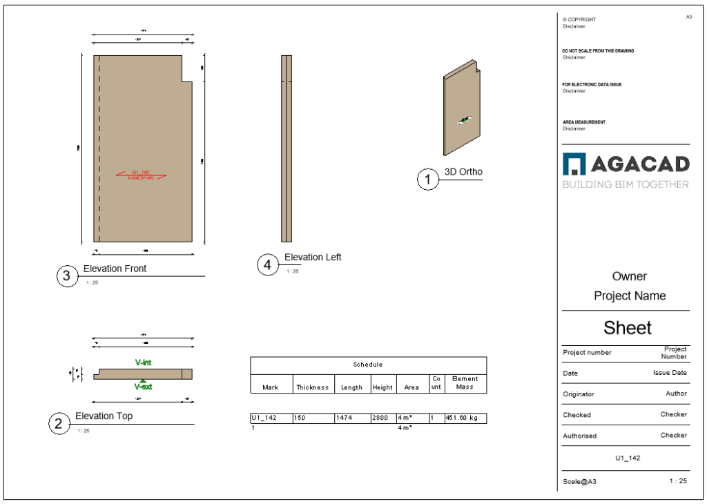
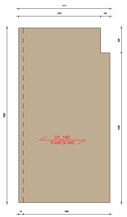
</td><td></td></tr></tbody></table>

### **STEP 5: Create frame**

First, let’s run the ‘**Number Types**‘ command, which will number all host elements, namely, walls, floors, and roofs:

<figure><img src="https://239424168-files.gitbook.io/~/files/v0/b/gitbook-x-prod.appspot.com/o/spaces%2FqtUsszuAWXIZhQhrvjnb%2Fuploads%2FAyp9bSlI6EXcscL2cbRm%2FNumber-types.png?alt=media&#x26;token=48499468-37a8-48a9-8420-dfd01ffa3db2" alt=""><figcaption></figcaption></figure>

That’s it! Now select all of the walls, floors, and roofs, and use ‘**Create Frame**‘.

{% hint style="warning" %}
*Make sure you select elements from the wall, floor, or roof category — not parts!*
{% endhint %}

In this example, CLT panels with half-lap connections were generated:

<figure><img src="https://239424168-files.gitbook.io/~/files/v0/b/gitbook-x-prod.appspot.com/o/spaces%2FqtUsszuAWXIZhQhrvjnb%2Fuploads%2Fq9i1vQhHSsJNWlgUtJlP%2FCreate-Frame.png?alt=media&#x26;token=83eea38e-864c-4b1b-8beb-690d1e5f0b6c" alt=""><figcaption></figcaption></figure>

Result:

<figure><img src="https://239424168-files.gitbook.io/~/files/v0/b/gitbook-x-prod.appspot.com/o/spaces%2FqtUsszuAWXIZhQhrvjnb%2Fuploads%2FgWIOd2NkZdctvafjLmdJ%2FAfter-Create-Frame-command.png?alt=media&#x26;token=ebe102bb-4620-424e-a6a6-552ba8451b9f" alt=""><figcaption></figcaption></figure>

{% hint style="info" %}
I demonstrate the process from ***STEP 5: Create Frame*** in the webinar embedded below. Various ways of modifying the frames after they have been created are also shown. Start viewing from about 10:45.
{% endhint %}

{% embed url="<https://youtu.be/jU3S6PhbTDA?t=645>" %}

### **STEP 6: Insert connections common for CLT structures**

Now, let’s insert half-lap connections for L and T connections in our wall panels.

Select all wall Parts, and then use ‘**Auto-Insert**‘:

<figure><img src="https://239424168-files.gitbook.io/~/files/v0/b/gitbook-x-prod.appspot.com/o/spaces%2FqtUsszuAWXIZhQhrvjnb%2Fuploads%2FFxbjkvmzIowJEqh24vK7%2FAuto-insert-connections.png?alt=media&#x26;token=4fa22296-cc20-4a43-88ea-8c829cbcd0d4" alt=""><figcaption></figcaption></figure>

As a result, half-lap connections were created for L-joins and also, cuts for T-joins:

<figure><img src="https://239424168-files.gitbook.io/~/files/v0/b/gitbook-x-prod.appspot.com/o/spaces%2FqtUsszuAWXIZhQhrvjnb%2Fuploads%2Fp93Iw8uVhvgOr6izSbUs%2FL-and-T-connections.png?alt=media&#x26;token=88098e5a-0092-4fac-a44d-a8f091c25d9b" alt=""><figcaption></figcaption></figure>

### **STEP 7: Number elements**

Some of the parameter values that are common for CLT structures can be **entered manually**, before numbering the panels based on predefined rules.\
\
For example, I can enter:

<table><thead><tr><th width="264"></th><th></th><th data-hidden></th></tr></thead><tbody><tr><td><strong>FM_CLT_Visual Q_Int</strong><br><strong>FM_CLT_Visual Q_Ext</strong></td><td>Visual quality for interior and exterior sides of the panel</td><td></td></tr><tr><td><strong>FM_CLT_Grain Dir</strong></td><td>Grain direction (ON – horizontal, OFF – vertical)</td><td></td></tr><tr><td><strong>FM_CLT_Unit Number</strong></td><td>Unit number – it can represent separate buildings in the project or something else of that nature</td><td></td></tr></tbody></table>

<figure><img src="https://239424168-files.gitbook.io/~/files/v0/b/gitbook-x-prod.appspot.com/o/spaces%2FqtUsszuAWXIZhQhrvjnb%2Fuploads%2FFvGcDgnkPz5MGVO0nMSi%2FNumbering-elements-manually.png?alt=media&#x26;token=8a839511-7d1f-4281-a5b5-46a78279503d" alt=""><figcaption></figcaption></figure>

In the image below, in the **Numbering Rules** window (1), you can choose all needed rules for various categories (like Walls, Parts, Structural Framing, Structural Connections, etc.) and their parameters, which should be filled in, in a single configuration.

Also, you’ll be able to assign configurations that should be used with ‘**Number Types**‘ and ‘**Number Elements**‘ commands (2):

<figure><img src="https://239424168-files.gitbook.io/~/files/v0/b/gitbook-x-prod.appspot.com/o/spaces%2FqtUsszuAWXIZhQhrvjnb%2Fuploads%2F9EhSwdmAoXBlxQUCDkjh%2FNumbering-Rules.png?alt=media&#x26;token=0d51c426-2f85-4360-8436-45652e138fa5" alt=""><figcaption></figcaption></figure>

Now, when we’ll run the ‘**Number Elements**‘ command, all elements will be numbered by the sample configurations assigned in the ‘Numbering Rules’. As you can see, **‘FM\_CLT\_Part Level**‘ was calculated and filled in. Also ‘**Mark**’ parameter value, and so on:

<figure><img src="https://239424168-files.gitbook.io/~/files/v0/b/gitbook-x-prod.appspot.com/o/spaces%2FqtUsszuAWXIZhQhrvjnb%2Fuploads%2FvFnlCNqCUskS2LhXvwKl%2FNumber-Elements.png?alt=media&#x26;token=679e3744-47fb-49ee-bf35-e9d708d945e4" alt=""><figcaption></figcaption></figure>

### **STEP 8: Insert tags**

After numbering the elements, we can select all needed parts and use ‘**Insert Tags**’. After that, 3D Tags will be inserted, where you’ll see previously entered Visual Quality parameter values for the interior and exterior sides of the panel:

<figure><img src="https://239424168-files.gitbook.io/~/files/v0/b/gitbook-x-prod.appspot.com/o/spaces%2FqtUsszuAWXIZhQhrvjnb%2Fuploads%2FRJOCCyfbnNKjGqBEKUCR%2FInsert-Tags.png?alt=media&#x26;token=c303b2f0-8008-4f67-9e64-b914d073092f" alt=""><figcaption></figcaption></figure>

*<mark style="color:red;">These 3D Tags are Structural Framing category elements that are being used as Tags.</mark>*

{% hint style="warning" %}
*If you don’t want to see these tags in the 3D View, you can hide them, but you should still insert them, as we’ll be using these 3D Tags to tag panels when creating shop drawings in the following step.*\
\&#xNAN;*If you do not insert them, then the panels will not have tags in the shop drawings!*
{% endhint %}

*<mark style="color:red;">Of course, these are only sample configurations and can be adjusted to your needs later.</mark>*

### **STEP 9: Create shop drawings**

Finally, you can select all numbered and tagged parts and use ‘**Create Assembly**’. In this example, I’m creating an assembly of a wall panel, so I’ll choose the ‘**CLT Wall Panel**’ sample configuration:

<figure><img src="https://239424168-files.gitbook.io/~/files/v0/b/gitbook-x-prod.appspot.com/o/spaces%2FqtUsszuAWXIZhQhrvjnb%2Fuploads%2FLgOb2rWn2wn1Fj1PWCHc%2FCreate-Assembly.png?alt=media&#x26;token=64502b53-d940-433b-b49e-96000b172eb5" alt=""><figcaption></figcaption></figure>

You’ll find all generated views and schedules in the **Project Browser** under **Assemblies**. All views will have dimensions, and tags added automatically:

<figure><img src="https://agacad.com/wp-content/uploads/2022/05/Shop-Drawing-1024x730.png" alt="technical drawing"><figcaption></figcaption></figure>

We chose horizontal grain direction for this panel in **STEP 7**, so now, in the Elevation Front view, we have the automatically added tag showing us the horizontal direction, as well as the Mark (*U1\_142*) of this part and the visual quality (*V-ext (V-int)*):

<figure><img src="https://agacad.com/wp-content/uploads/2022/05/Elevation-Front-View.png" alt="technical drawing of a wall panel"><figcaption></figcaption></figure>

{% hint style="info" %}
All sample configurations used in this explanation can be found and modified under ‘**Configs**’, here:
{% endhint %}

<figure><img src="https://agacad.com/wp-content/uploads/2022/05/Where-to-find-sample-configurations.png" alt="software UI"><figcaption></figcaption></figure>

<br>
